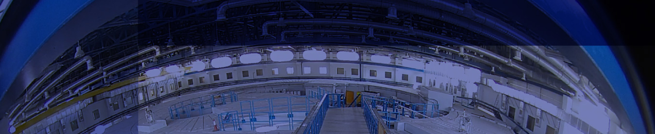
The lattice of the storage ring is based on a Double Bend Achromat (DBA) structure. The ring consists of 16 identical half-super-periods (cells), with a central combined function bending magnet (BM) (dipole with field gradient), two focusing quadrupoles (QF), two defocusing quadrupoles (QD), and 4 sextupoles (two SF and two SD) with the embedded correctors. The combined function magnets perform most of the vertical focusing, that is complemented by the QD quadrupoles. All the magnets of a cell are mounted on a single common girder.
Dipoles
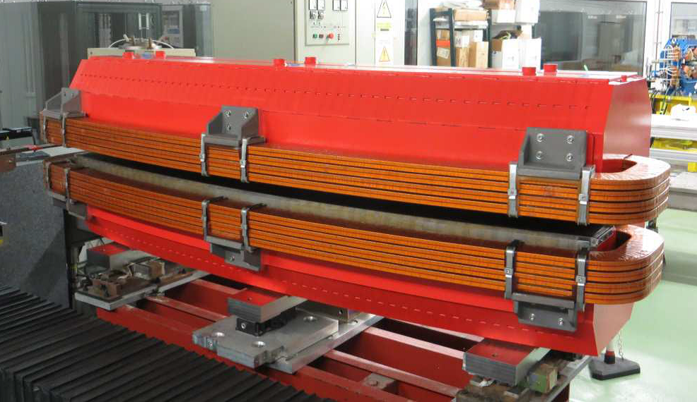
The SESAME storage ring has 16 dipole magnets with the maximum magnetic field of 1.455 T and a field gradient of - 2.79 T/m. The dipole is a ‘C’ type magnet, with parallel end and with the yoke laminations stacked parallel according to the nominal bending radius; the full gap is 40 mm at the transverse magnetic center.
The BM has bending angle 22.5°, with magnetic flux 0.4657T and 1.4554T at injection and top energies respectively. Main parameters of the combined function BM at 2.5 GeV operation are listed in the following table. The BM has bending angle 22.5°, with magnetic flux 0.4657T and 1.4554T at injection and top energies respectively. Main parameters of the combined function BM at 2.5 GeV operation are listed in the following table.
| Number of magnets | 16 |
| Bending radius [mm] | 5729.58 |
| Bending angle [deg] | 22.5 |
| Central field [T] | 1.455 |
| Field gradient [T/m] | -2.79 |
| Central vertical gap (total) [mm] | 40 |
| Magnetic length [mm] | 2250 |
| Current [A] | 494 |
| Number of turns (total) | 96 |
| Conductor size [mm] | 13 × 11, ⌀ 6 |
| Current density [A/mm2] | 4.3 |
| Number of pancakes | 8 |
| Resistance (total) [mΩ] | 83 |
| Inductance (total) [mH] | 145 |
| Power [kW] | 20.2 |
| Water temperature rise [°C] | 10 |
| Pressure drop [bar] | 7.0 |
| Flow rate / magnet [l/min] | 29.0 |
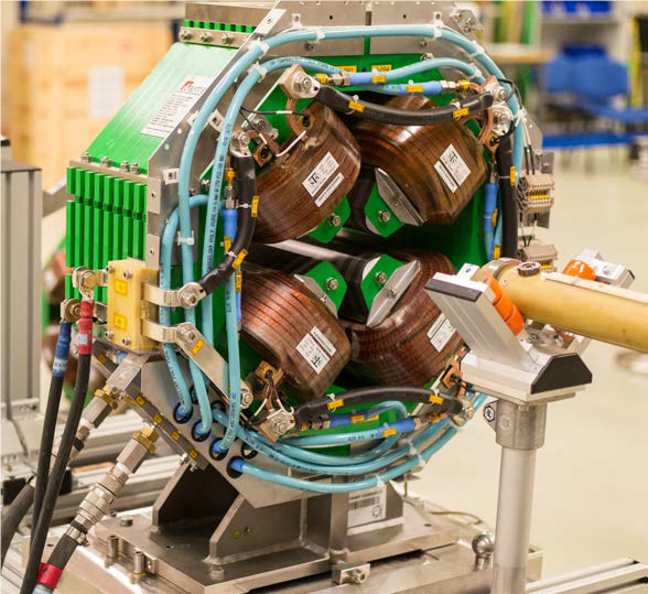
Quadrupoles and Sextupoles
The storage ring quadrupoles are 64 ones, half of them are focusing while the other half are defocusing. They are of two different lengths and strengths. The 64 sextupoles are identical and divided equally into focusing and defocusing ones. They accommodate additional coils to provide a horizontal/vertical dipole and a skew quadrupole terms. The main parameters of quadrupoles and sextupoles are summarized in the following tables.
| QF | QD | |
|---|---|---|
| Number of magnets | 32 | 32 |
| Field gradient [T/m] | 16.5 | -7.6 |
| Aperture radius [mm] | 35 | 35 |
| Field at pole tip [T] | 0.58 | 0.27 |
| Magnetic length [mm] | 308 | 135 |
| Current [A] | 238 | 195 |
| Number of turns (per pole) | 34 | 19 |
| Conductor size [mm] | 8.5 × 8.5, ⌀ 4 | 8.5 × 8.5, ⌀ 4 |
| Current density [A/mm2] | 4.0 | 3.3 |
| Resistance (total) [mΩ] | 38 | 12 |
| Inductance (total) [mH] | 21 | 3 |
| Power [kW] | 2.1 | 0.4 |
| Water temperature rise [°C] | 5 | 5 |
| Pressure drop [bar] | 5.0 | 5.0 |
| Flow rate / magnet [l/min] | 6.1 | 1.4 |
| SF | SD | |
|---|---|---|
| Number of magnets | 32 | 32 |
| Sextupole strength [T/m2] | 63.4 | -108.9 |
| Aperture radius [mm] | 37.5 | 37.5 |
| Field at pole tip [T] | 0.09 | 0.15 |
| Magnetic length [mm] | 123 | 123 |
| Current [A] | 60 | 103 |
| Number of turns (per pole) | 15 | 15 |
| Conductor s | 6.5 × 6.5, ⌀ 3.5 | 6.5 × 6.5, ⌀ 3.5 |
| Current density [A/mm2] | 1.9 | 3.2 |
| Resistance (total) [mΩ] | 23.8 | 23.8 |
| Inductance (total) [mH] | 2.9 | 2.9 |
| Power [W] | 86 | 252 |
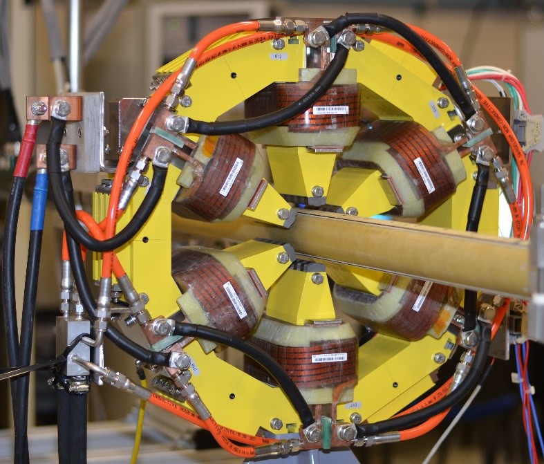
Correctors
In SESAME due to space shortage the horizontal, vertical, and skew quadrupole correctors are embedded in the sextupole magnets. In order to have reasonable field uniformity, 6 coils are used for horizontal correctors and 4 coils for the vertical one. The design kick value for each single corrector magnet is 0.5 mrad @ 2.5 GeV. The nominal parameters of the correctors are reported in the following table.
| VC | HC | SQ | |
|---|---|---|---|
| Integrated strength | 4.16 mTm | 4.16 mTm | 90 mT |
| Current [A] | 10 | 8 | 19 |
| Number of turns (per pole) | 80 / 40 | 80 | 40 |
| Conductor size [mm] | 3.75 × 1.6 | 3.75 × 1.6 | 3.75 × 1.6 |
| Current density [A/mm2] | 1.7 | 1.3 | 3.2 |
| Resistance (total) [mΩ] | 388 | 374 | 106 |
| Inductance (total) [mH] | 17 | 23 | 3.8 |
| Power [W] | 35 | 23 | 40 |
Insertion Devices
An insertion device is a sequence of short bending magnets of opposite polarity driving the beam in an oscillatory motion. The radiation from each bend therefore accumulates in a preferential direction producing very high spectral flux. Nowadays, insertion devices are not only used to provide higher flux compared to bending magnet sources, but also to produce radiation with different polarization characteristics.
Undulators are built with short periods and medium fields as opposed to wigglers, which are usually optimized for large magnetic fields resulting in longer periods with negligible enhancement by interference. Embedding the short magnets into an iron yoke allows the generation of a higher magnetic field and/or a better control of the field pattern. Most undulators and wigglers are made of permanent magnets. In order to vary the peak field of such a device, the only method is to change the magnetic gap. In the particular case of the pure permanent magnet arrays, allows a precise estimation of the peak field at any gap and period.
Conventional insertion devices with a planar, nearly sinusoidal magnetic field, essentially produce linearly polarized radiation with an electric field perpendicular to the plane of the undulator magnetic field. For some scientific applications, it is important to produce circularly polarized radiation. There exists a number of different types of insertion design optimized to generate such radiation. The most successful of such undulators known as Apple II. The magnetic field generated by an Apple II is extremely flexible. For a given gap and period the field in whichever polarization state is close to the highest that one can design. These properties of flexible polarization and field efficiency are the reason for the success of the Apple II undulator. The magnet structure has four sub-assemblies, two above and two below the beam axis. Contrary to a conventional planar device where only the gap is a free parameter, an Apple II undulator is built with three degrees of freedom, namely the magnetic gap and the longitudinal positions the magnet arrays. By moving the sub-assemblies longitudinally relative to each other, the relative strength of the transverse components of the magnetic field is altered leading to change in the polarization of the emitted radiation.
Material Science Wiggler
The SESAME Material Science (MS) beamline accommodate X-ray diffraction (XRD) experiments in the energy range between 5 and 25 keV. The MS source is 2 m long wiggler located along the I09 straight section. The main wiggler parameters are summarized in the following Table.
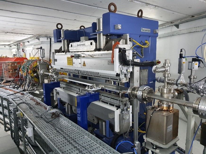
| Overall W61 length (m) | 2 |
| Wiggler gap (mm) | 12 |
| Period length (mm) | 60.5 |
| Number of periods | 33 |
| Magnetic material | NdFeB |
| Pole material | CoFe |
| Maximum field (T) | 1.38 |
| Deviation parameter K | 7.8 |
| Critical energy (keV) | 5.8 |
| Total power @ 400 mA (kW) | 6.01 |