Abstract
The SESAME Materials Science MS beamline for X-ray diffraction XRD applications is presently under construction. The beamline is based on donated components previously installed at the Swiss Light Source, but modifications in the beamline design have been introduced to match the characteristics of the SESAME storage ring. A wide range of XRD applications will be possible at the beamline. The commissioning of the beamline is expected to be in the December 2019.
MS Source
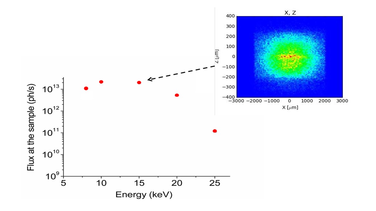
The MS source is 2 meter long wiggler W61 located along the I09 straight section. The main wiggler parameters are summarized in table 1 while these parameters were used to calculate the beamline flux spectrum (see figure 1). The minimum magnetic gap is 12 mm which have been decided based on the possible minimum vacuum chamber height available at SESAME during the first operation period.
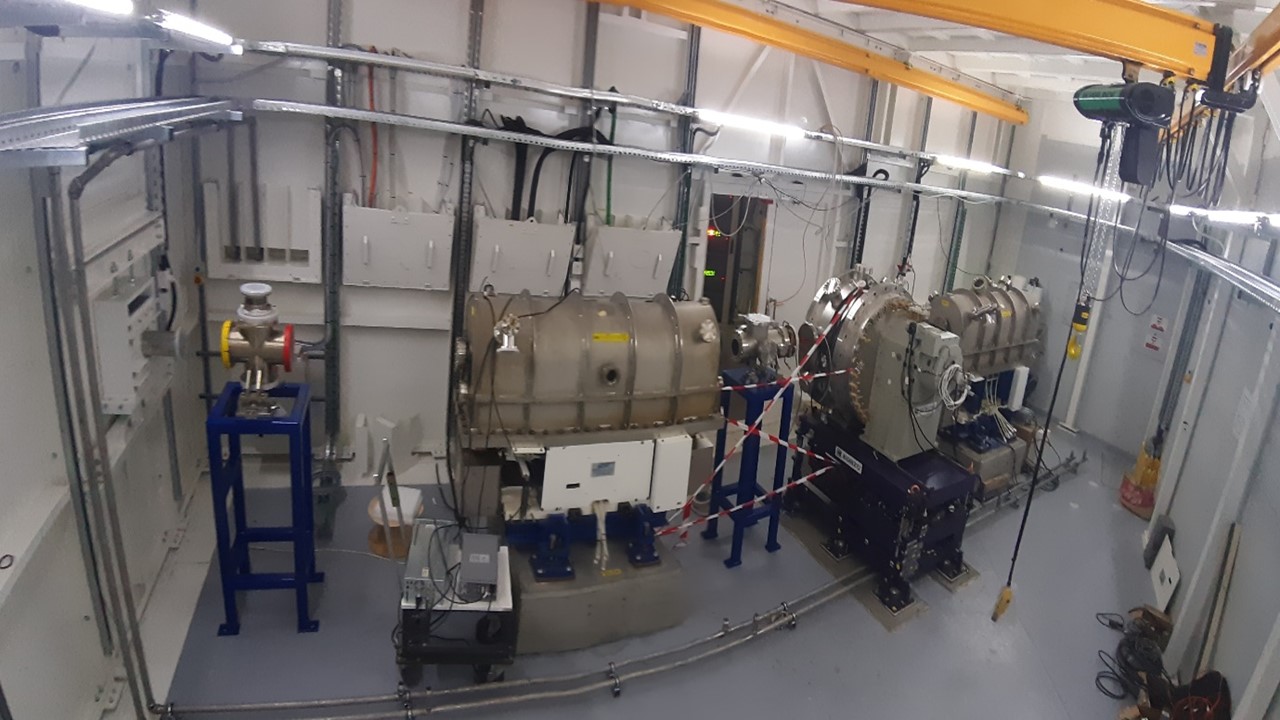
The installation of the wiggler inside SESAME storage ring was started in January 2019 and completed in mid-February 2019, while some machine tests were carried out successfully at low electron current afterwards to investigate the wiggler effect on the SESAME machine stability. Figure 2 shows the MS wiggler inside the SESAME storage ring after completing the installation.
This wiggler will produce reasonably high flux up to 25 keV with about 6000 Watt of radiation power. Therefore the front end station; mainly fixed masks and filter; will deal with this high power in order to protect the optical components from damage. The flux distributions in the front end before and after the major front end components are shown in figure 3.
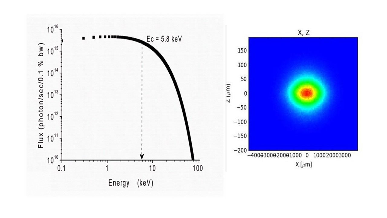
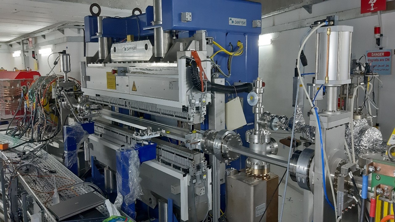
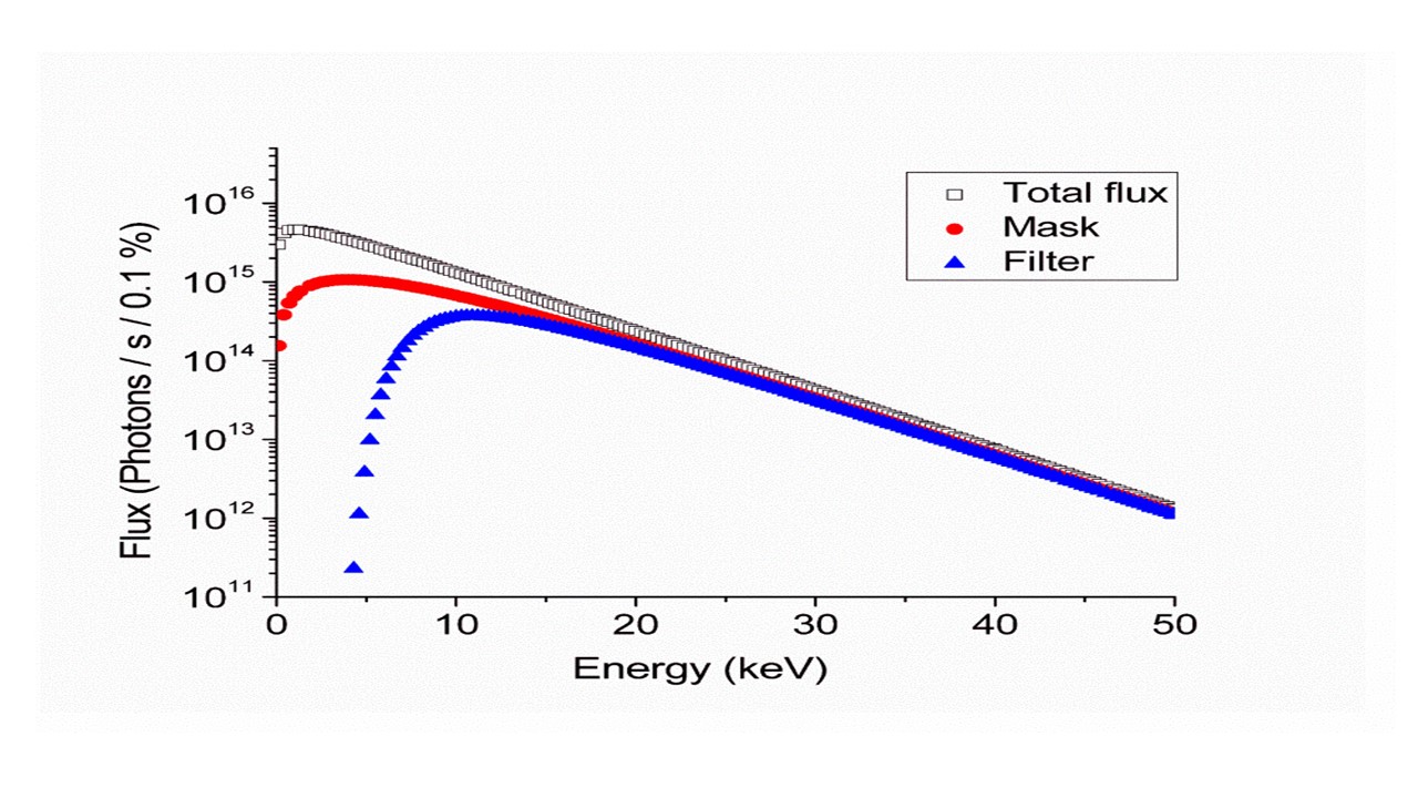
Table 1 the main parameters of the MS wiggler source
| Overall W61 length (m) | 2 |
| Wiggler gap (mm) | 12 |
| Period length λ_w (mm) | 60.5 |
| Number of periods | 33 |
| Magnetic material | NdFe:B |
| Pole material | CoFe |
| Maximum field (T) | 1.38 |
| Deviation parameter K | 7.8 |
| Critical energy Ec (keV) | 5.8 |
| Total power @ 400mA (kW) | 6.01 |
Beamline Layout
The optical components are aimed at selecting the desired beam energy; focus the beam in horizontal and vertical planes, and to improve the energy resolution. The energy selection is accomplished by a Kozhu double crystal monochromator in which the first crystal is a water cooled Si crystal and the second one is a sagittal Si crystal that can be used to focus the beam in the horizontal plane. The second crystal has two perpendicular translational degrees of freedom. The routine operations of the monochromator will be based on Si(111) diffraction planes, while Si(333) diffraction planes will be used to obtain a narrow bandwidth at high energies.
The monochromator will be preceded by a one-meter length Rh-coated mirror which will vertically collimate the divergent beam in order to improve the energy resolution. A second mirror similar to first one will be located after the monochromator and will focus the beam in the vertical direction by changing its radius of curvature. The rms slope errors of the collimating and focusing mirrors are 3.56 µ rad and 2.63 µ rad respectively. Both mirrors are tilted to grazing angles in order to optimize simultaneously the angular acceptance of the incoming beam and the mirror reflectivity.
Table 2 the location of the major beamline components from the wiggler centre
| Components | Distance (m) |
| Front end | |
| Wiggler W61 | 0 |
| Fixed mask | 8.11 |
| Photon shutter | 8.43 |
| Rotating filter | (glassy carbon) 9.67 |
| Horizontal slits | 10.23 |
| Vertical slits | 10.79 |
| Radiation stopper | 11.43 |
| Diamond window | 13.57 |
| Optics | |
| Fast Absorber | 14.12 |
| Filters | 14.25 |
| Collimating Mirror | 15.58 |
| Wire Beam Position Monitor BPM | 16.68 |
| Double Si crystal Mono | 17.55 |
| Radiation stopper | 18.44 |
| Focusing mirror | 20.01 |
| Photon shutter | 21.79 |
|
Experimental |
|
| Experimental | 33.4 |
Major Beamline specifications
SHADOW3, through its last distribution ShadowOui [2] was used to best optics performance in terms of flux, beam shape and energy resolution at the samples which are the major parameters of interests for XRD community. In order to provide an accurate ray-tracing simulation, not only geometrical factors were taken into account, but also physical factors like absorption/scattering of the initial photon beam by several optical elements were considered. In other words, taking into account the following properties:
- Absorption coefficient of Screens/Filters
- Reflectivity of Mirrors/Multilayers
- Diffraction profile of Crystals
- Slope errors of Mirrors
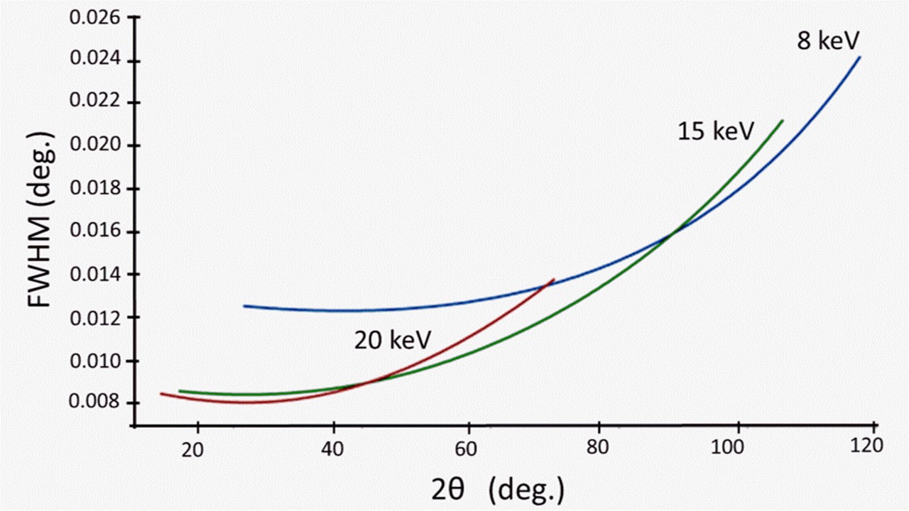
The beamline ray tracing analysis at 10 keV estimates the flux at the sample to be in the order of 1013 (photons/s), the energy resolution is about 2 eV and the effective beam size at the sample of 300 x 2800 μm2. Investigations of microstruture will be possible as the instrumental broadening, resulted from simulating the diffraction pattern for a standard material (see figure 6), is in the order of 0.01o at 15 keV.
Table 3: the major beamline specifications
| Energy range (keV) | 5 - 25 |
| Accepted divergence (m rad2) | 0.23 (V) x 1.5 (H) |
| Flux at the sample at 10 keV (photons/s) | 1.6 ×10¹³ |
| Energy resolution | (eV) ~ 2 |
| Effective beam size at the sample (FWHM) (μm2) | 300 (v) x 2800 (h) |
EXPERIMENTAL STATION
Diffractometer:
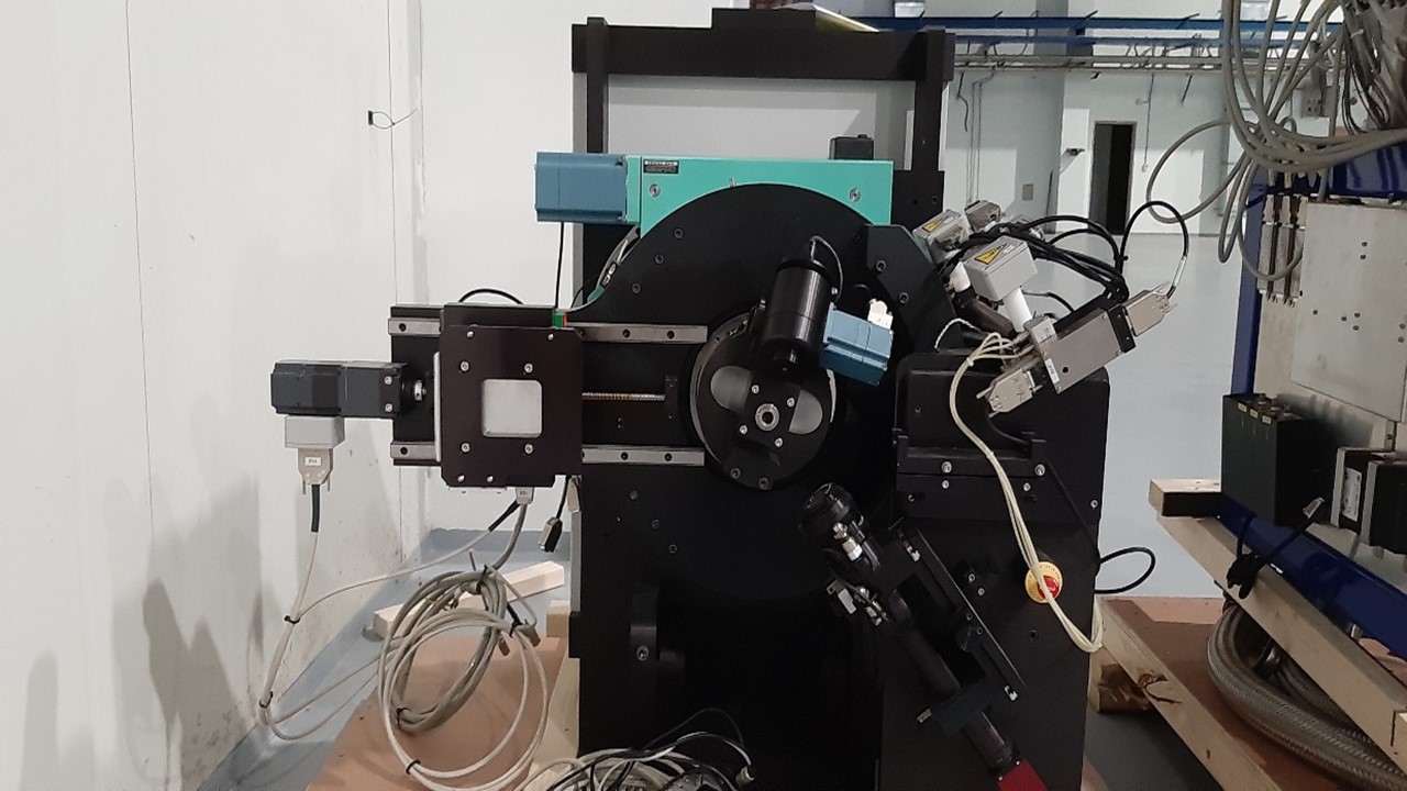
An old diffractometer (Kappa) was donated from Diamond synchrotron which was originally used at I19 beamline, the image of the diffractometer is shown in figure 7. Some modifications in the diffractometer are then necessary to fit the main requirements of powder diffraction experiments.
Detection systems:
Detector I (Fast area PILATUS3 300K):
A Pilatus 300K detector was donated by DECTRIS company, to be used for X ray diffraction experiments in SESAME, the main technical specifications of the detector are listed below:
- Area: 83.8 x 106.5 mm2
- Pixel Size: 172 x 172 µ m2
- Time resolution (readout): 7 ms
- Framing rate: 500 Hz
- Weight (detector head): 7.5 Kg
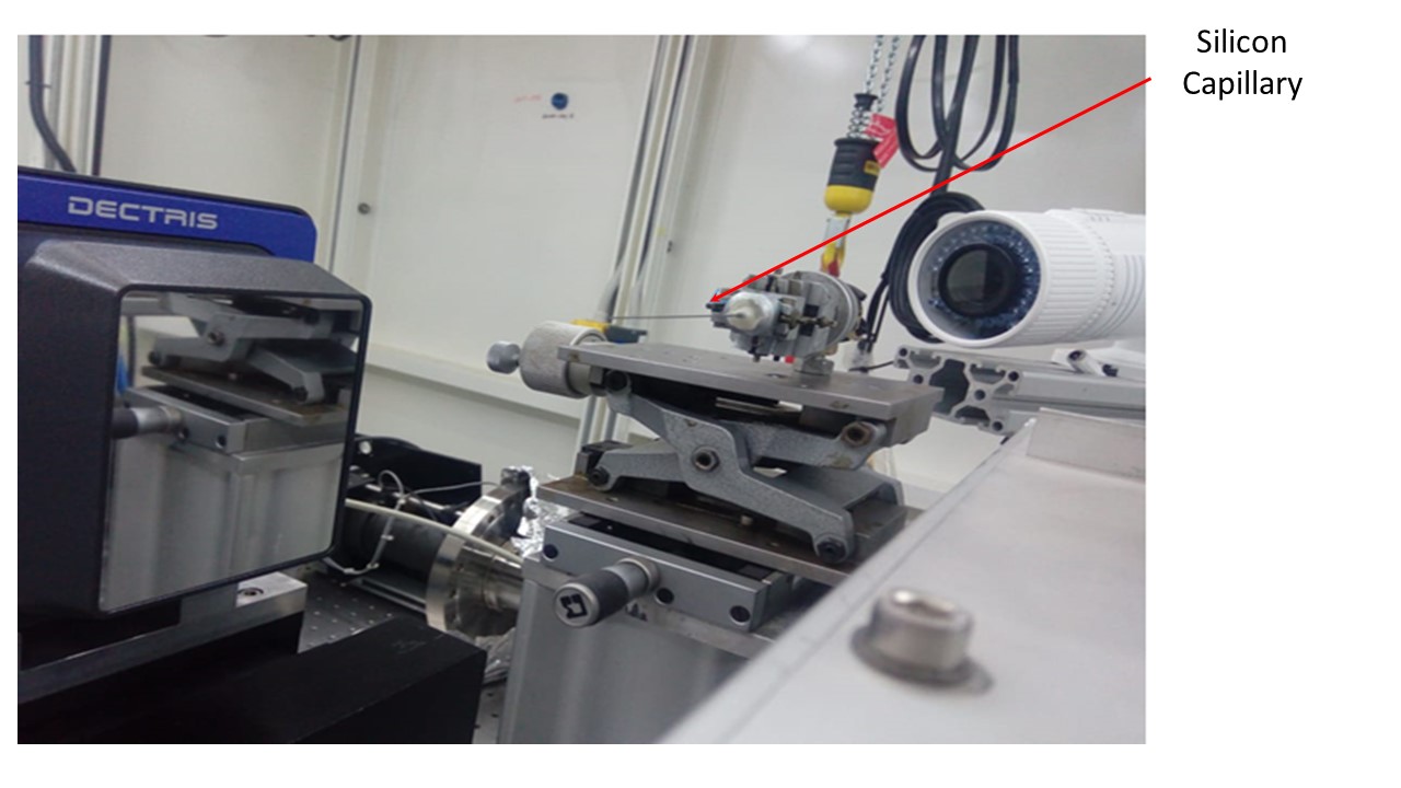
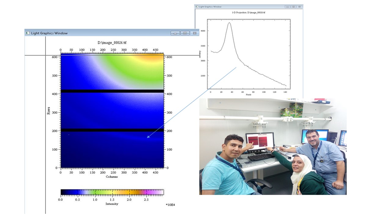
Some preliminary tests for the Pilatus detector were carried out at the SESAME XAFS beamline with X ray beam, where silicon capillary was hit by the X ray beam and then the first peak of diffraction pattern was collected on the detector; Experiment set up is shown in figure 8. the result of the first diffraction image was collected out of the experiment and was then investigated and processed.
Detector II (Point detector coupled with crystal analyser)
This detector is intended to be used for XRD experiments which require high angular resolution, however experimental time in this case will be relatively longer that the Pilatus detector.
Samples’ Stages and Environments: (Information will be published soon)
Contact
| Person | Description/Position | Email Address |
|---|---|---|
| Mahmoud Abdellatief | Beamline responsible | mahmoud.abdellatief@sesame.org.jo |
Acknowledgements
The hard work of those who are involved in the design, constructions and installation of the MS beamline at SESAME site is strongly appreciated.
We would like also to thank DECTRIS Company for offering a Pilatus 300K detector, especially Dr. Dubravka Sisak Jung for her efforts to the make this donation possible.
Special thanks go to Dr. Luca Rebuffi; who is an expert optics scientist at Elettra synchrotron; for his assistance on the beamline ray tracing calculations.
References
- M. Abdellatief, L. Rebuffi, H. Khosroabadi, M. Najdawi, T. Abu-Hanieh, M. Attal, and G. Paolucci, Powder Diffraction Journal, doi:10.1017/S0885715617000021
- Patterson, B.D., Abela, R., Auderset, H., Chen, Q., Fauth, F., Gozzo, F., Ingold, G., Kühne, H., Lange, M., Maden, D., Meister, D., Pattison, P., Schmidt, Th., Schmitt, B., Schulze-Briese, C., Shi, M., Stampanoni, M. & Willmott, P.R., 2004, Nucl. Instr. Meth. Phys. Res. B, 540, 42
- Rebuffi, L. & Sanchez del Rio, M., 2016, J. Synchrotron Rad., doi:10.1107/S1600577516013837